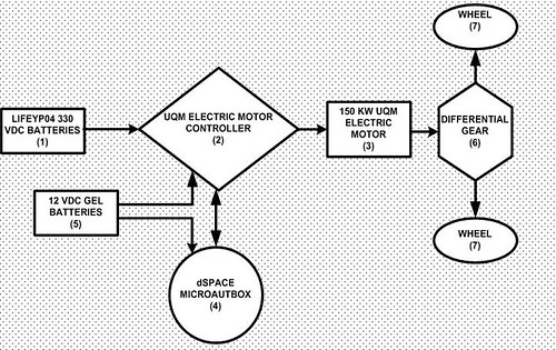
The electric minibus consists of 100 cells of LiFeP04 battery supplying 330 VDC, battery management system, an electric motor of UQM having continuous power of 100kW with its driver, a dSpace Microautobox 1401 vehicle controller, two quantities of 12 VDC gel batteries to drive Microautobox and UQM motor controller. The electric minibus does not require any gear box because the control software is available and electric motor supplies sufficiently high torques at low voltage levels. There is only a differential gear with the ratio of 5.28 to amplify the revolutions of the electric motor.The general schematic is below:
dSpace Microautobox is used to control the vehicle which require power supply within the range from 6 VDC to 40 VDC; hence, 12 VDC gel batteries are used. The
vehicle controller design process can be evaluated in two parts: Vehicle Basic Control such as driving forward/backward, starting the movement, cutting off the
voltage and Vehicle Communication Network (namely, CAN Communication). The control design logic is below:
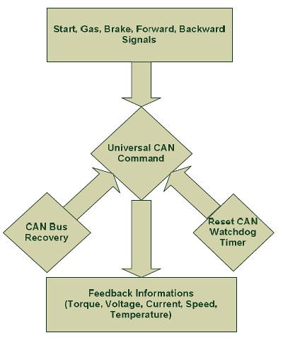
At the beginning, vehicle signals are transmitted as an universal command and then they are processed with the control network. The basic operations are designed and sent to the universal command block in dSpace toolbox as shown in Figure. The acceleration signal is triggered by a potentiometer determining the vehicle speed. Moreover, brake signal comes from the brake pedal which enables vehicle to stop. In addition to them, the start command is used to give the battery voltage (330 VDC) to the EM in order to prepare the vehicle to run. Furthermore, the forward and backward signals command the vehicle in forward and backward directions. All these signals and others are transferred from the command blocks which are connected with Microautobox pin outs to universal command block. Universal command is a CAN communication block including control types which are torque control, voltage control or speed control that transmits the signals as the message packets. When the commands are processed, the feedback information is necessary to understand the conditions such as voltage, torque, speed, current, temperature. The CAN control set up is used to organize the data type, baudrate and some other information about the communication process such as module type, module number. In the real time application of electric minibus, the baud- rate is 500 kbit/s, the torque control is used, identifier type is 11 bit. The EM address is described to communicate with the Microautobox. Thanks to CAN Watchdog property, no communication problem has been observed. Watchdog status enables to understand communication error and the Watchdog Timer can reset the situation as shown in flowchart. CAN Watchdog Status including commands and errors is used to avoid the communication problem at the electric motor side. Likewise, in Microautobox, the CAN communication errors are averted by CAN Bus Recovery. In Figure, the status is related with the address priority and the recovery module reset the process when default is done.
The electric minibus first movement is shown in video below:
After the some trials and experiences, Ahmet and the group increase the level and their first experince shows that they can use the minibus with the 65 km/h and then they also increase to 72 km/h. The video below shows the 65 km/h speed: